| Contact Us For Quotation | Email: 464560351@qq.com | Whatsapp&Wechat:+8618620373879 |
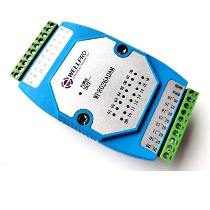
Xtester- WP8026ADAM 16 Channel WELLPRO DI MODBUS RTU Communications Digital Input Module Optocoupler Isolated
Main Parameters
Digital input channels: 16 channels (active - low). Operating temperature range: -20 ℃ - 70 ℃. External power supply: DC9V - 30V/2W. Isolation protection: 1500VDC. Installation method: Standard DIN - rail installation or screw - mounting. Dimensions: 125 * 73 * 35 mm. |
Features
RS485 MODBUS RTU standard communication, can be networked with configuration software, PLCs, industrial touch - screens, etc. Equipped with communication and input/output status indicators. The communication circuit is designed with lightning protection and anti - interference features. Can be widely used for signal acquisition and control of industrial field devices. |
Usage Instructions
Connect the computer and the module with an RS485 converter. Connect a 12V or 24V external power supply to the module and turn on the power. To avoid unnecessary damage, check that the power supply is correctly connected before power - on. Open the debugging software, select the corresponding module model, and enter the function debugging or parameter - setting interface. Set the correct communication parameters and open the communication port. Select appropriate setting, acquisition, and control options. |


 English


